All Messages

Q: contacter le vendeur... where is the link for contact dealer?

Asked by MARECHAL on 2023-11-12 01:07:19

Tex2002ans Hello, if you have any questions, you can consult us directly.

2023-11-14 03:34:21 Helpful (0)
Submit
Answers (1)

MARECHAL Bonjour. je l'ai depuis 3ans. Il consomme 55mA donc sur accu Li ion ok pour des heures.presser 1 fois et MAINTENIR . A la trousieme proposition...definition 100Hz. on relache .Une pression maintenue donne 200KHZ 1KHz et 100Hz . Relacher. pour ajuster osc local en FM ou en UHF 450 Mhz c'est bon...Une fois l' ajustable du quartz remplacé par un BON CV qui ne bouge pas (donc pas un Murata). Une fois ajusté, tranquille sur des mois. Manque juste un mini VCXO mais vu le coût... TRES BON produit

spatulex 02/03/2018
0
Comments (1)

MARECHAL HelloNormally code colour of transfo IFT is the following one: IFT1: Yellow IFT 2: White and IFT3: Black moreover measure the resistance of bobin... The black in the secondary has less turns. If you invert the IFT, it can work but badly. (Not enough sensibility.)For the bo oscillator, generally it is red... But once.. Green. Damage that he have there no indication on shield case such as; OSC, IFT1 , IFT2 and IFT3. For the transfo of output , the secondary has very low resistance... ( HP

thehobe 26/09/2016
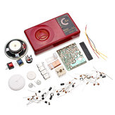
I built this device in a couple of hours but am dissatisfied with the finished unit. The batteries do not fit properly and pop out their position due to the battery contacts. I had to glue in some foam to properly hold the batteries. The soldering of the antenna wires is quite difficult --even with my 35 years experience as an Analog design engineer with massive experience in building projects. The location of the IF transformer coils requires you to translate chinese symbols on the schematic using the internet but even then, The first IF coil slug is black and not red as some websites show in pictures of the completed unit. There are several websites mixing up the white and yellow IF cans. The proper placement is: B2-black, B3-White, B4-yellow, and B5-Green---at least that is what the schematic says. My radio worked but it is not an example of a good AM radio. You can listen to the ball game on it but don't expect much more. The amplifier transformers are also not identified on the schematic--I used the green as the first or primary transformer, B6 and red as the output transformer, B7. I built the circuit just to have a little fun as I am retired now (but not very old). AM ferrite antennas are very directional. The tuning dial "needle" sticker is VERY basic and unattractive. I think you are better off buying a working, old transistor radio from Ebay for better fit and finish if you want better tuning, sound and battery retention. I did like the use of two AA batteries over the traditional 9V battery for cost and availability. That is actually one of the key reasons I purchased this radio.
7
Comments (2)

MARECHAL Yes, i test it with germanium transistors PNP 'change positive to négetive and electrochimique also diodes sil. he work perfectly also.this schematic is malicious and simple. Only one problem is no CAG but for price...perfect!I put new order for modify this one for LW due in France MW finish...it is small challenge attractive also for no many money of couse.

vsurducan 02/11/2016
3
Comments (1)

MARECHAL Si vous en avez Utilisez un peu de trichloréthylène pour recoller.laisser 12H mini sous pression (elastique) et apres c'est solide et réparé.C'est un bon petit poste...dommage que le plastique de la boite ne soit pas de bonne qualité.

riton83 10/08/2017
0
Comments (1)